A practical engineering breakdown of how vacuum operated semiconductor wafer robots grip, move, and protect silicon wafers inside fabs. Learn the mechanics, sensors, vacuum levels, and failure modes that decide yield.
How Does Vacuum Operated Semiconductor Wafer Robot Works
A vacuum operated semiconductor wafer robot moves a silicon wafer worth thousands of dollars without scratching it, tilting it, or dropping a single particle on its surface. It does this hundreds of times per hour, in the dark, inside a sealed steel chamber, with position accuracy measured in tens of microns. Understanding how it actually works matters because wafer handling is one of the few places in a fab where a mechanical mistake instantly destroys product that took weeks to build.
This guide explains the real mechanics: how vacuum suction grips a wafer, how the robot arm geometry is chosen, how sensors verify wafer presence, what happens when vacuum is lost, and why vacuum grippers stop working entirely inside a process chamber. It is written for process engineers, equipment technicians, automation buyers, and students who want the working detail rather than a marketing summary.

Quick Answer: A vacuum operated wafer robot grips a wafer by pulling air through small ports in a flat end effector, creating a pressure difference that holds the wafer against the paddle. Servo-driven arms then rotate, extend, and lift along programmed paths, while vacuum sensors, laser mappers, and encoders confirm the wafer is present and correctly seated before every move.
What a Vacuum Operated Wafer Robot Actually Is
Definition: A vacuum operated semiconductor wafer robot is a precision automation system that uses negative air pressure through a flat blade end effector to hold a wafer, combined with servo-controlled rotary and linear axes to transfer that wafer between cassettes, load locks, aligners, and process modules.
Three subsystems make it work together:
- The end effector (paddle or blade) contacts the wafer backside and applies vacuum.
- The kinematic arm provides rotation, radial extension, and vertical travel.
- The control and sensing layer verifies grip, position, and wafer presence before allowing motion.
Remove any one of these and the machine stops being a wafer robot and becomes a hazard. The vacuum alone holds nothing if the arm accelerates too aggressively. The arm alone is useless if the controller cannot prove a wafer is actually on the blade.
How the Vacuum Grip Physically Holds a Wafer
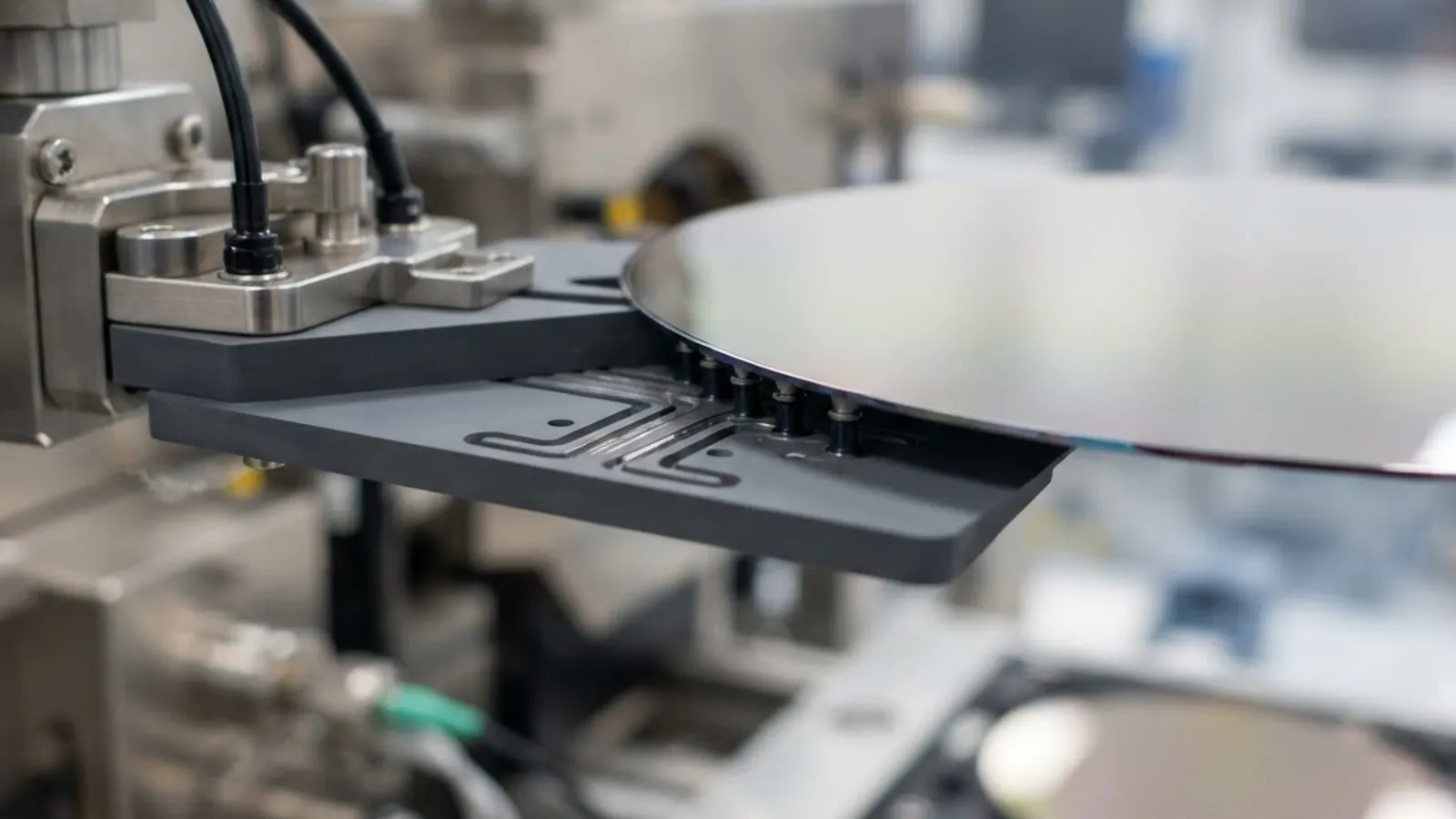
The grip is pure differential pressure, not magic adhesion. A vacuum generator, either a mechanical pump or a compressed-air venturi ejector, evacuates a small channel network machined into the end effector. When a wafer covers the ports, atmospheric pressure on the top surface presses the wafer down onto the blade.
The holding force follows a simple relationship:
Holding force = effective sealed area x pressure differential
A paddle with 400 mm2 of sealed port area and a 60 kPa differential generates roughly 24 N of clamping force. A 300 mm silicon wafer weighs only about 0.13 kg, roughly 1.3 N, so the safety margin is large in static conditions. The real constraint is dynamic: during rapid rotation the wafer experiences lateral inertial load, and the limiting factor becomes friction between wafer and blade, not raw suction. That is why acceleration profiles are tuned rather than maximized.
Why the Ports Are Small and Recessed
End effector ports are deliberately small, polished, and recessed into shallow grooves. Large flat contact areas trap particles and can imprint stress marks on thin wafers. Recessed grooves distribute the pull force while keeping physical contact area low, typically only a few percent of the wafer backside. Materials matter too: alumina ceramic, silicon carbide, and PEEK are common because they are dimensionally stable, low-particulating, and resistant to the chemistries drifting out of process chambers.
Step by Step: One Complete Wafer Transfer Cycle
Here is what happens in a single move, in the order the controller executes it:
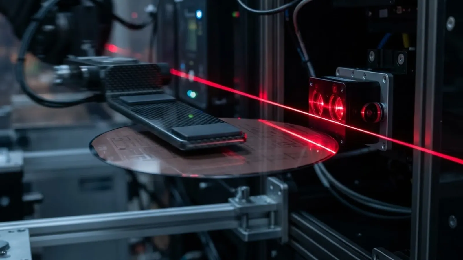
- Mapping. A through-beam or reflective sensor scans the cassette or FOUP to record which slots hold wafers and flag cross-slotted or double-stacked wafers.
- Approach. The arm rotates to the target station angle and sets blade height just below the wafer edge.
- Insertion. The blade extends under the wafer with millimeter-level clearance above and below.
- Lift and seal. A short vertical rise contacts the wafer while vacuum is already flowing.
- Grip verification. A vacuum switch or analog pressure transducer confirms the pressure has dropped below the trigger threshold, proving the wafer sealed the ports.
- Retract and transfer. The arm withdraws and moves along a taught, collision-checked path.
- Place and release. The blade positions over the destination, vacuum is vented, and the wafer settles onto pins or a chuck.
- Confirm empty. Pressure returns to ambient, confirming release. Only then does the next cycle begin.
A modern atmospheric robot completes this in roughly 6 to 10 seconds per wafer, which is how a single tool sustains throughput of well over 200 wafers per hour.

Arm Geometries and Why Engineers Choose Them
Wafer robots are not generic industrial arms. Their geometry is optimized for one motion: straight radial extension with zero wafer rotation.
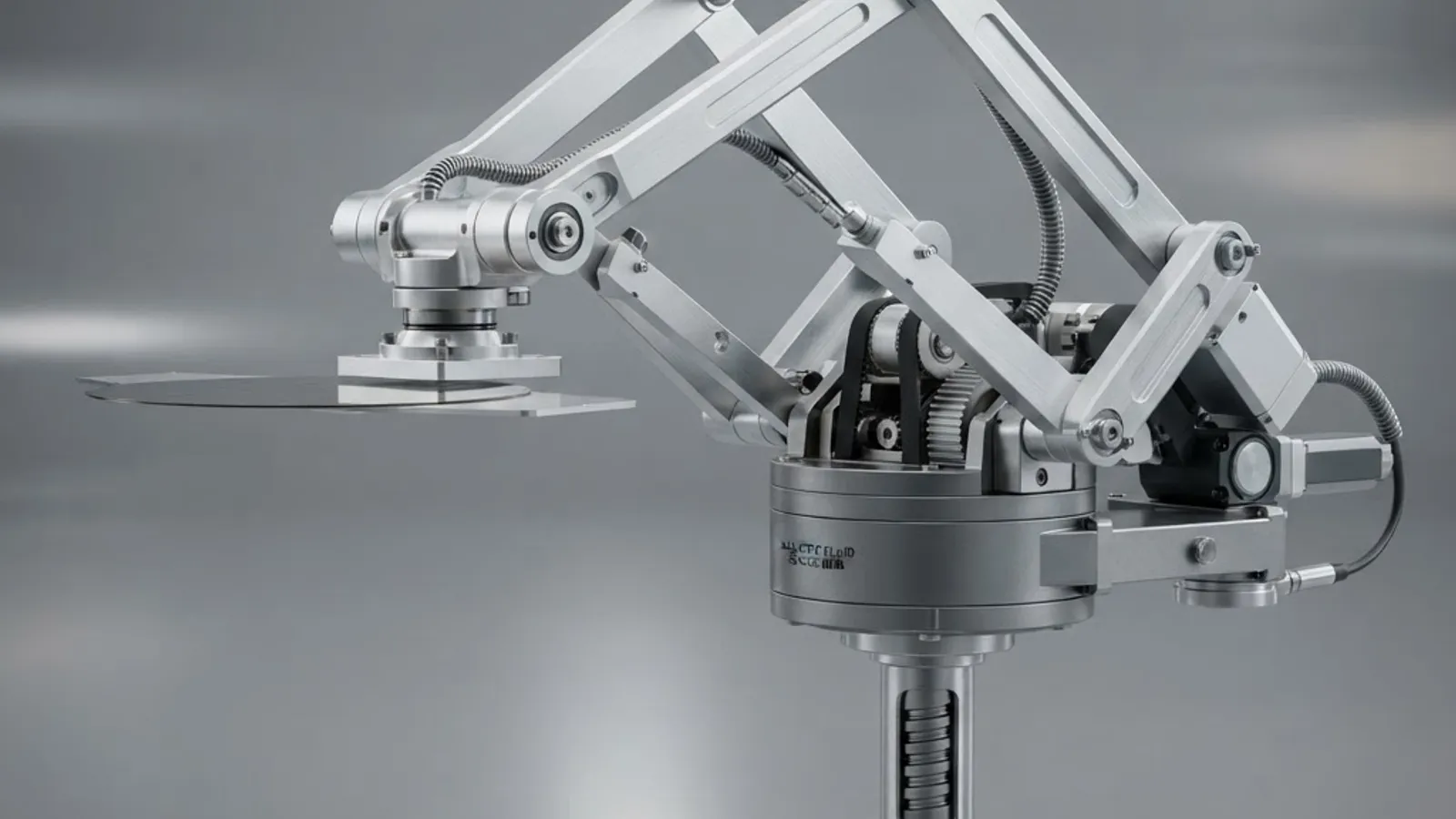
- Frog-leg linkage. Two coupled arms convert differential rotation into perfectly straight blade travel, giving excellent rigidity and a compact footprint.
- SCARA and dual-SCARA. Rotary joints in a horizontal plane, stiff vertically, easy to seal, and the most common design in atmospheric front ends.
- Dual-arm or dual-blade. Two independent paddles allow swap moves, removing a wafer and inserting the next in one visit to a chamber. This can cut module idle time by 20 to 40 percent.
- Linear track robots. A SCARA mounted on a rail serves long rows of load ports in high-volume equipment front end modules.
Atmospheric Vacuum Grip vs Vacuum Environment Handling
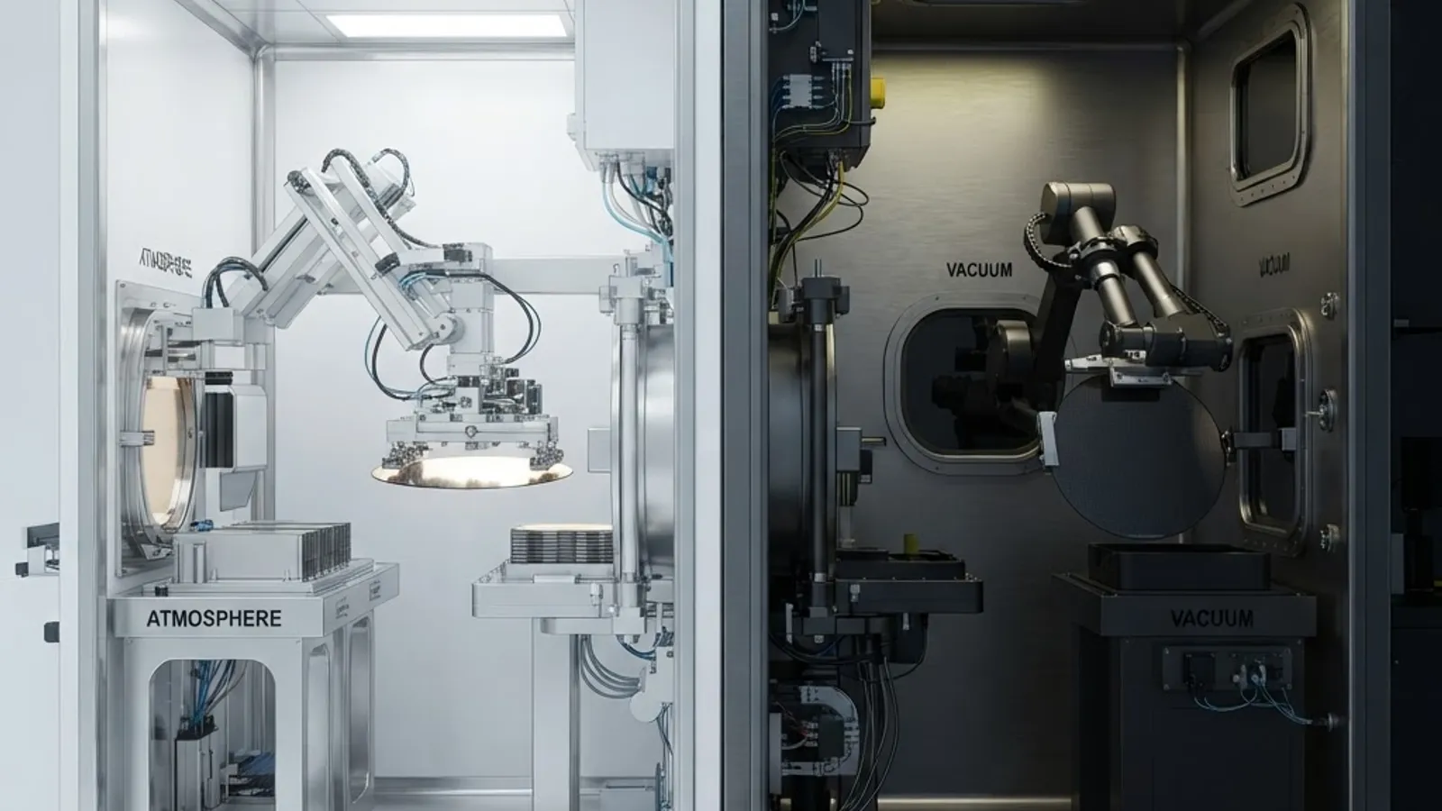
This is the single most misunderstood point in the topic, and it is worth stating plainly: a suction gripper cannot work inside a vacuum chamber. With no surrounding atmosphere there is no pressure differential to create holding force. Robots operating in vacuum transfer modules use edge contact, friction paddles with high-grip pads, or electrostatic chucks instead.
| Factor | Atmospheric Robot (Vacuum Suction) | Vacuum Environment Robot |
|---|---|---|
| Gripping method | Negative pressure suction ports | Edge grip, friction pad, or electrostatic |
| Works in vacuum chamber | No | Yes |
| Typical location | Equipment front end module, load port, aligner | Vacuum transfer module between process chambers |
| Motor and cable sealing | Standard, open to clean air | Magnetic fluid seals, vacuum rated feedthroughs |
| Lubrication | Conventional low-particle grease | Low outgassing vacuum grease |
| Slip risk driver | Vacuum loss or clogged port | Acceleration exceeding friction limit |
| Relative cost | Lower | Significantly higher |
The Sensing Layer That Prevents Broken Wafers
Vacuum grip is only trustworthy because it is continuously measured. Practical fab systems layer several independent checks:
- Vacuum pressure feedback. Analog transducers report the actual level, so a slow leak from a partially blocked port is caught as a trend before it becomes a drop.
- Wafer present sensing. Fiber optic or capacitive sensors on the blade confirm presence independently of pressure.
- Slot mapping. Detects missing, double, or cross-slotted wafers before insertion.
- Pre-aligner and notch detection. A rotating chuck with a line sensor finds the wafer center offset and notch angle, then the robot corrects placement in software.
- Encoder and torque monitoring. Servo torque spikes reveal contact, binding, or worn bearings.
In well-instrumented lines, a vacuum loss event triggers immediate controlled deceleration rather than an emergency stop, because abrupt braking is itself a common cause of wafer slip.
Contamination Control: The Hidden Design Requirement
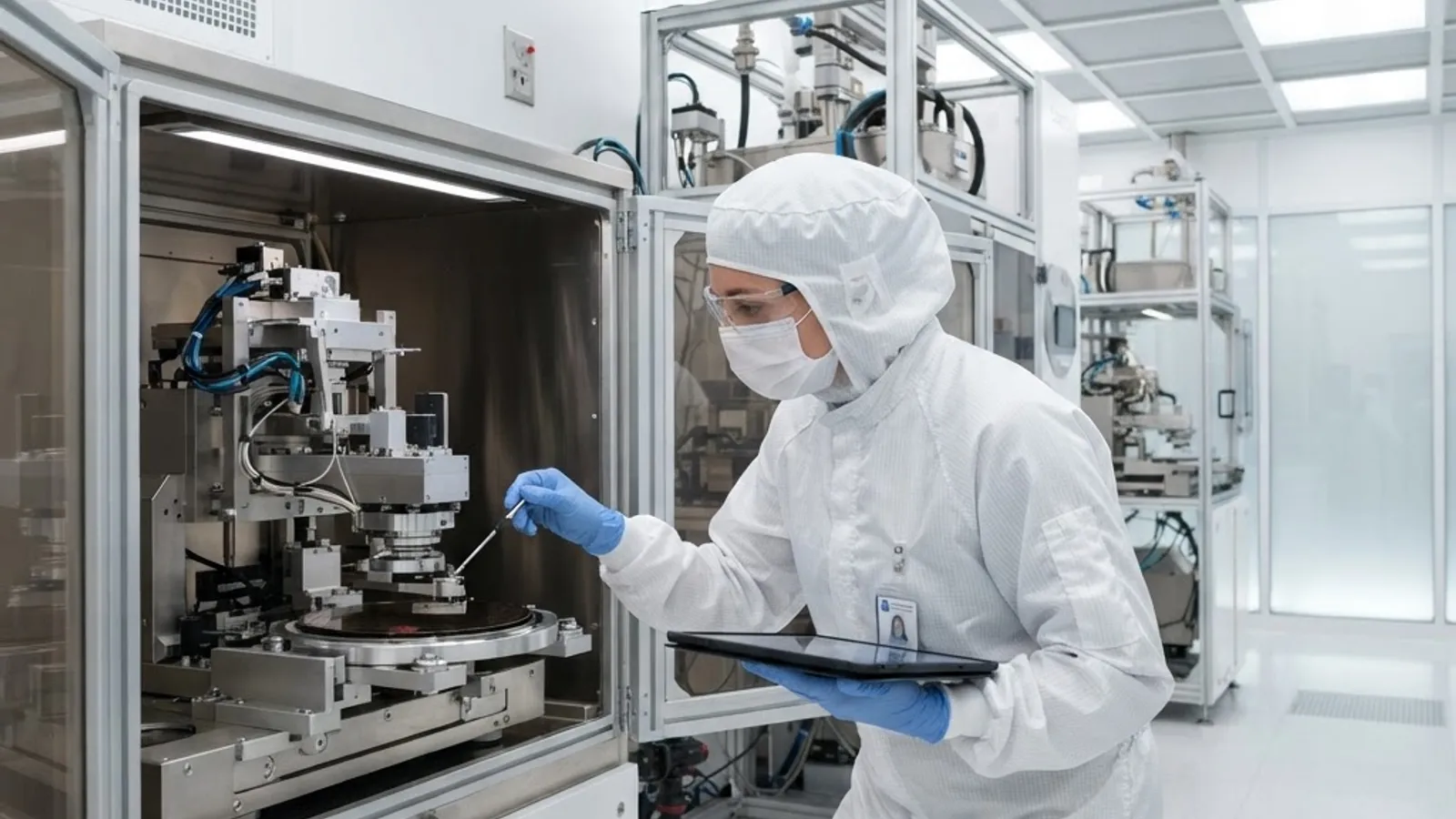
A wafer robot is judged as much on cleanliness as on speed. Advanced nodes are extremely sensitive to particles, and cleanroom standards such as ISO 14644-1 Class 3 permit only a handful of particles per cubic meter at the smallest measured sizes. Every moving joint is a potential particle source, so designers use sealed bearings, internally routed cables, downstream exhaust paths, and enclosed harmonic gearboxes.
Two maintenance habits protect yield more than anything else. First, inspect and clean end effector ports on a fixed schedule, because a single clogged port silently reduces holding force. Second, verify teach positions after any service, since a blade a fraction of a millimeter too high will scrape wafer backsides for weeks before anyone notices the defect signature.
Where Software and AI Improve Wafer Handling
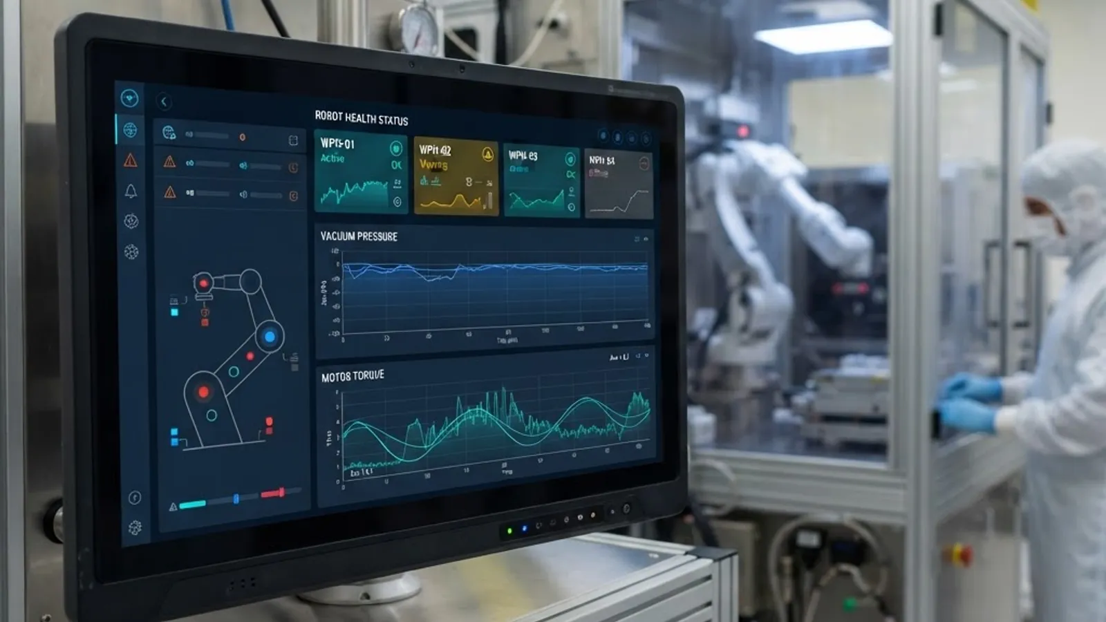
Modern wafer robots stream vacuum pressure, motor torque, cycle time, and temperature data to equipment monitoring layers over standards like SECS/GEM. Analyzing that data turns hard failures into scheduled maintenance: a rising torque baseline signals bearing wear, and a gradually shrinking vacuum margin signals port contamination or a tubing leak.
Given that unplanned equipment downtime is among the largest controllable costs in high-volume manufacturing, predictive monitoring pays for itself quickly. Teams building this kind of monitoring and analytics layer often pair robot telemetry with custom dashboards and anomaly detection models, an area covered by WebPeak artificial intelligence services. For broader engineering, software, and digital build support, ZoneTechify and WebPeak both work on the data and interface side of industrial automation projects.
Common Failure Modes and Their Real Causes
- Wafer slip during rotation. Almost always excessive acceleration or a contaminated blade surface, not insufficient pump capacity.
- Intermittent vacuum error. Usually a pinched tube, aging solenoid valve, or one blocked port rather than a failing pump.
- Backside scratches. Teach point drift or a worn pad edge on the paddle.
- Placement offset. Skipped pre-alignment or thermal growth of the arm during long production runs.
- Particle excursions after service. Residual debris from disassembly and inadequate purge time before restarting production.
Key Takeaways
- Vacuum grip force equals sealed port area multiplied by pressure differential; a typical paddle produces roughly 20 to 30 N against a 300 mm wafer weighing about 1.3 N.
- Suction grippers only function at atmosphere. Inside vacuum transfer modules, robots use edge grip, friction, or electrostatic chucking.
- A full transfer cycle runs about 6 to 10 seconds, enabling tool throughput above 200 wafers per hour.
- Dual-blade robots reduce chamber idle time by roughly 20 to 40 percent through swap moves.
- Grip reliability comes from layered sensing: analog vacuum feedback, wafer present sensors, slot mapping, and pre-alignment.
- Cleanliness targets under ISO 14644-1 Class 3 drive sealed bearings, internal cable routing, and low-outgassing lubricants.
- Most slip incidents trace to acceleration or contamination, not pump capacity.
Frequently Asked Questions (FAQ)
How does a wafer robot hold a wafer without damaging it?
It pulls air through tiny recessed ports in a flat ceramic or PEEK blade, so atmospheric pressure presses the wafer gently onto the paddle. Contact area stays only a few percent of the wafer backside, spreading force evenly and avoiding point stress, scratches, or imprint marks on the polished surface.
Can a vacuum suction robot work inside a vacuum chamber?
No. Suction needs surrounding atmospheric pressure to create a differential, and inside a vacuum chamber there is none. Robots working in vacuum transfer modules instead use edge gripping fingers, high friction pads, or electrostatic chucks, and they use magnetic fluid seals to keep motors isolated from the vacuum.
What happens if the vacuum fails while a wafer is moving?
The controller detects the pressure change through a vacuum switch or transducer and commands a controlled deceleration rather than an abrupt stop, since hard braking often causes slip. The robot holds position, raises an alarm, and waits for operator verification before any further motion is allowed.
How accurate is a semiconductor wafer handling robot?
Repeatability is typically in the range of tens of microns at the wafer, achieved through servo encoders, rigid linkage geometry, and taught positions. Final placement accuracy also depends on a pre-aligner that measures wafer center offset and notch angle so the controller can compensate before placement.
How often should wafer robot end effectors be maintained?
Most fabs inspect and clean end effector ports and pads on a fixed preventive schedule, often monthly or by wafer count, and re-verify teach positions after any service. Trending vacuum margin and motor torque data lets teams replace worn parts before a slip or particle excursion occurs.
Why are wafer robots so expensive compared to industrial arms?
Cost comes from cleanroom-grade construction, not payload. Sealed bearings, low-outgassing lubricants, internal cable routing, vacuum-rated feedthroughs, precision linkages, and layered safety sensing are all required to protect wafers worth far more than the robot itself over a single production shift.
Final Thoughts
A vacuum operated wafer robot works because three things stay in agreement: measured pressure, verified position, and controlled acceleration. When engineers troubleshoot handling problems, the fastest path is checking those three in that order. Treat the vacuum system as a measured process variable rather than a fixed utility, and most wafer handling failures become predictable and preventable.